Choosing the right Autonomous Mobile Robot (AMR) for your organisation
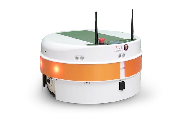
In an era where technology plays a crucial role in helping to solve daily challenges and improve efficiency, the integration of robotics into various sectors has become more important than ever. The TIAGo Base and the new TIAGo OMNI Base are examples of AMRs (Autonomous Mobile Robots), designed to improve operations and efficiency, offering unparalleled flexibility and customisation options to meet the unique needs of different industries. In this blog, find out more about how to customise TIAGo Base, and TIAGo OMNI Base, to meet the needs of your organisation.
You can have your own solution on top of a TIAGo Base robot, be it for healthcare, industry or office environments, working in less than a day. We have been receiving lots of inquiries asking us how easy and fast it is to integrate a solution on top of our mobile bases.
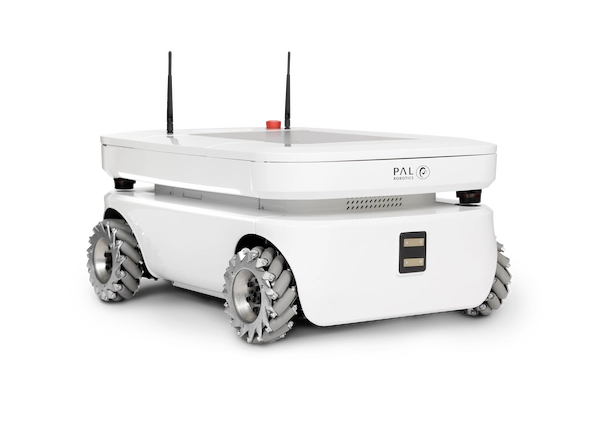
Introducing TIAGo OMNI Base: A robust platform that supports integration
TIAGo OMNI Base features an omnidirectional drive, and is designed to take customisation to the next level. It’s a robust platform that supports the mounting of specialised equipment, integration of advanced sensors, and customisation of functionalities, making the robot a versatile tool for various industries.
Customising Your TIAGo OMNI Base
1) Accessing the Service and Expansion panels
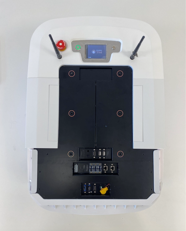
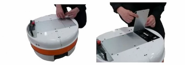
Start by removing the frontal top white cover, which is attached with magnets, to get access to the Service panel:
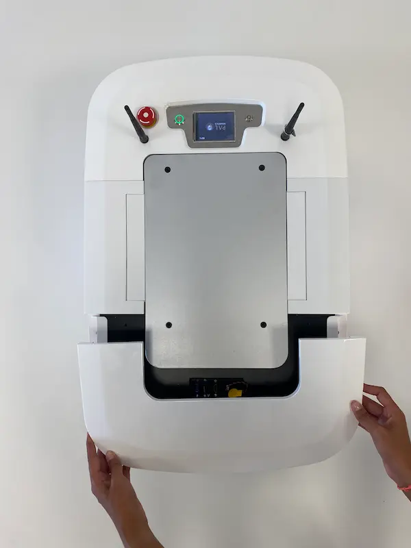
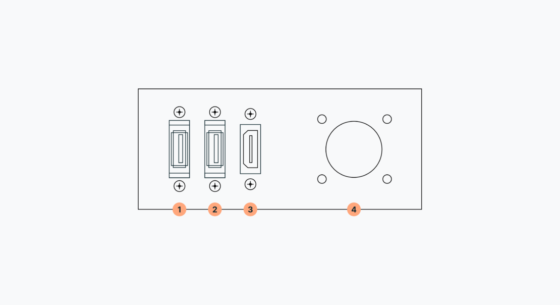
The Service panel provides you with two USB and one HDMI ports, as well as access to the BIOS Battery of the computer:
Note that the layout of this panel may change depending on the version
In the table below, you will find the Service panel specifications:
| Number | Specification |
| 1 | USB 3 |
| 2 | USB 3 |
| 3 | HDMI |
| 4 | BIOS Battery |
Then, unscrew the frontal top aluminium plate on the mobile base, as shown here:
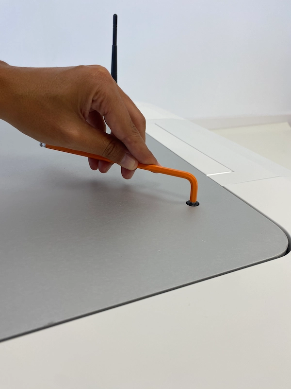
And proceed to remove the aluminium plate:
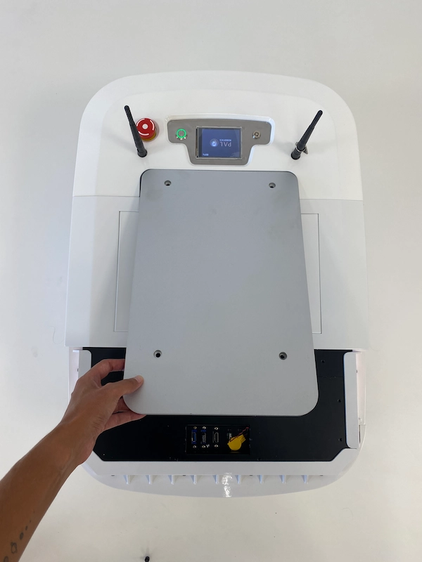
Once removed both the white cover and the aluminium plate, you will have access to the Expansion panel as seen below:
2) Expansion Panel
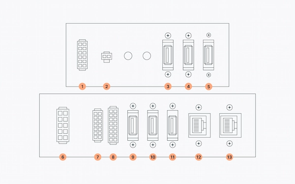
Find specifications for each port inside the Expansion panel in the infographic below:
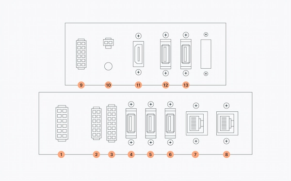
In the table below, you can see the specifications for the Expansion panel:
| Number | Specification |
| 1 | Power Connector |
| 2 | Communications Expansion, i.e. CAN (if ordered) |
| 3 | GPIOs |
| 4 | USB 3 |
| 5 | USB 3 |
| 6 | USB 3 |
| 7 | Ethernet |
| 8 | Ethernet |
| 9 | Reserved |
| 10 | Speaker |
| 11 | HDMI |
| 12 | USB 2 |
| 13 | USB 2 |
3. Power Connector
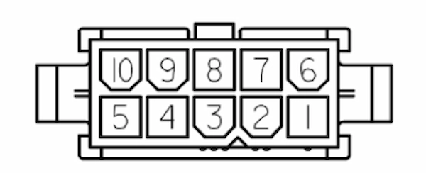
Located in the leftmost part of the Expansion panel, the Power Connector provides access to the robot’s battery up to 360W. The Power Connector is a connector type Molex 39012101, whose mating part is a Molex 39012100.
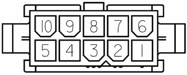
(mating part Molex 39012100)
In the table below, there is the pinout of TIAGo OMNI Base’s Power connector:
| Pin | Name/Short Description |
| 1 | |
| 2 | +12V output (max 4.5A shared with SICK laser if present) |
| 3 | Battery output (max 9A/pin) |
| 4 | Battery output (max 9A/pin) |
| 5 | Battery output (max 9A/pin) |
| 6 | |
| 7 | GND of 12V output |
| 8 | Battery GND |
| 9 | Battery GND |
| 10 | Battery GND |
Battery output pins are able to supply an external device with power up to 360 W. Battery output is within the range of 30 V to 42 V depending on the battery charge level of the robot. The robot is equipped with 2x Io-Li batteries of 36 V and 20 Ah each. It is recommended to use the all 3 battery output pins in parallel to divide current between them. The maximum current that can be provided through these battery pins is 10 A in total, approximately.
4. Communications Expansion Connector
To the immediate right of the Power Connector, you will find the Communications Expansions Connector. This connector gives access to the internal communication buses of TIAGo OMNI Base. There are two CAN for motors and actuators and one proprietary bus for sensors. Remember that only the CAN buses are available to the user and their speed is 1 Mbit/s. The Communications Expansion connector is a type Molex 43020-1400, whose mating part is a Molex 43025-1400.

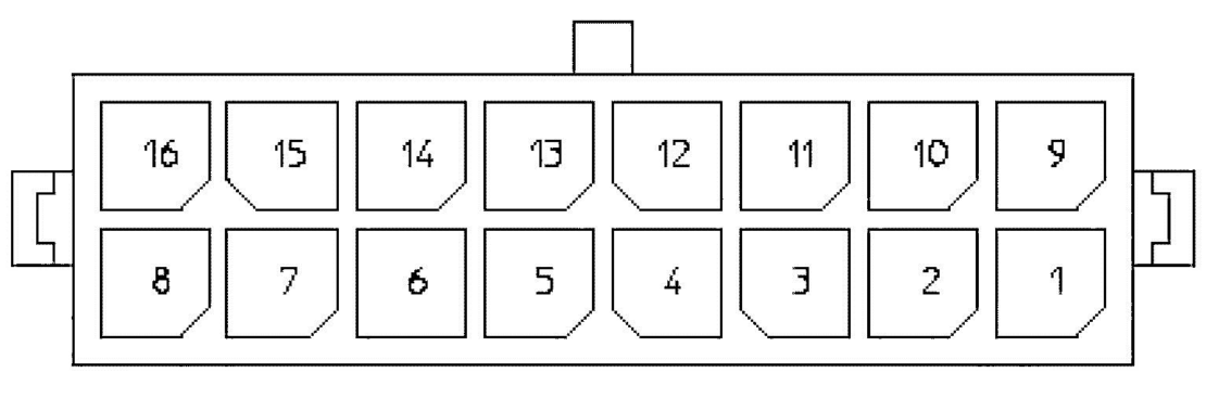
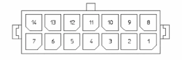
In the table below, you can see the pinout of the Communications Expansion connector with each pin matched to the corresponding name.
| Pin | Name/Short Description |
| 1 | CANL of LEFT bus |
| 2 | Shield of LEFT bus |
| 3 | CANH of LEFT bus |
| 4 | Reserved |
| 5 | Reserved |
| 6 | Reserved |
| 7 | n.c. |
| 8 | CANL of RIGHT bus |
| 9 | Shield of RIGHT bus |
| 10 | CANH of RIGHT bus |
| 11 | n.c. |
| 12 | n.c. |
| 13 | n.c. |
| 14 | n.c. |
5) GPIOs Connector
To the right of the Communications Expansion connector, there is the connector for General Purpose Input/Output pins. The connector provides access to General Purpose Input (GPI) and Output (GPO) pins. It is a Molex 43020-1600, whose mating part is a Molex 43025-1600.
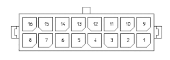
Check the table to see the GPIOs pinout:
| Pin | Name/Short description |
| 1 | |
| 2 | |
| 3 | |
| 4 | +5V |
| 5 | GPO 0 (5V TTL level) |
| 6 | GPO 1 (5V TTL level) |
| 7 | GPO 2 (5V TTL level) |
| 8 | GPO 3 (5V TTL level) |
| 9 | |
| 10 | |
| 11 | |
| 12 | GND |
| 13 | GPI 0 (5V TTL level) |
| 14 | GPI 1 (5V TTL level) |
| 15 | GPI 2 (5V TTL level) |
| 16 | GPI 3 (5V TTL level) |
General purpose outputs are referenced to pin 12 GND and are, by default, set to low level. On the other hand, general purpose inputs must be set using pin 4 +5V for high level and pin 12 GND for low level, and they have an internal default pull-up.
6) Accessing the Mechanical Interface
Remove the top plate to access the Mechanical Interface, which allows mounting structures up to 100 kg on top of the mobile base for integration use:
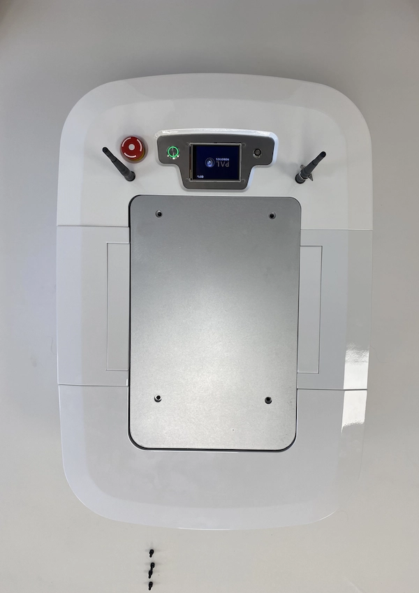
Once removed the covering plate, you will see the mounting points, that can hold a structure up to 100 kg, circled in red in the figure x below:

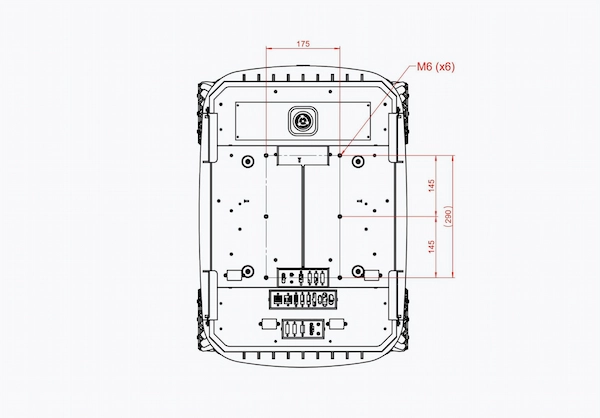
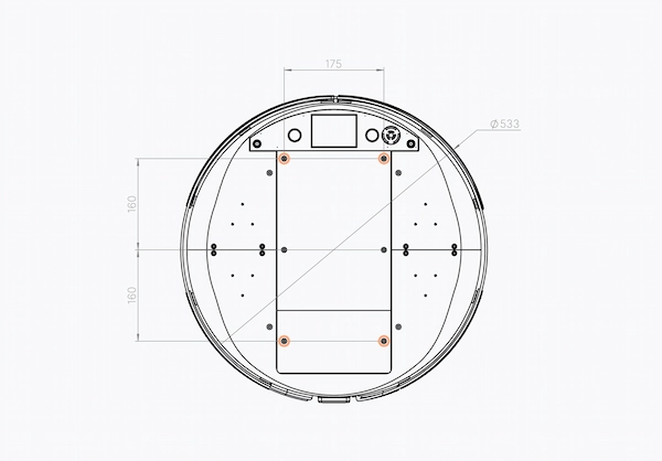
7) Mechanical Structure Dimensions
Get familiar with the dimensions of the mechanical structure of TIAGo OMNI Base for precise integration by taking a look at the technical drawing in figure x below where you will be able to see the mounting points, their dimensions and the distance between them.
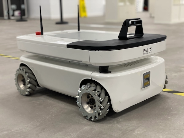
Examples of TIAGo OMNI Base integrations
Here are further examples of integrations on top of TIAGo OMNI Base:
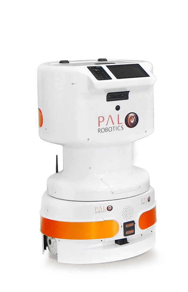
TIAGo Pro
Meet TIAGo Pro, our latest mobile manipulator built on a TIAGo OMNI Base. Designed for enhanced mobile manipulation capabilities, TIAGo Pro is the result of a compact and modular design made possible by the in-house integration on a TIAGo OMNI Base.

TIAGo OMNI RGB-D Camera Integration
The RGB-D camera add-on is a custom integration for TIAGo OMNI Base that attaches an RGB-D camera to the mobile base with an easily mountable magnetic panel designed to accommodate the attachment.
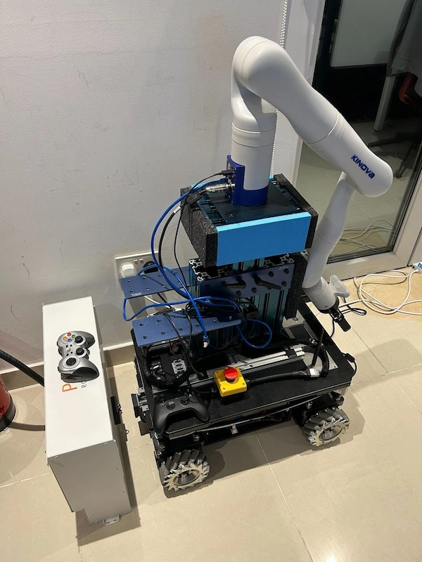
Kinova arm on TIAGo OMNI Base
In the figure 16 below, you can see the integration of a Kinova arm on top of a TIAGo OMNI Base at Technology Innovation Institute (TII) of Abu Dhabi.
TIAGo Base: A versatile platform offering customisation possibilities
TIAGo Base is a versatile solution that combines the flexibility of an AMR with the customisation possibilities offered by the robot’s design. Operating the TIAGo Base is straightforward, requiring no specialised training. The robot is designed to be user-friendly, with options like a Web GUI and integration with internal management systems.
TIAGo Base is one of our most flexible and adaptable robots, which is ready to help in tackling the pandemic. Below we explain how to choose and also easily change the robot’s upper body to meet your needs during the pandemic and beyond. You can read how it empowered workers at MAPCABLE.
TIAGo Base easily adapts to its environment and staff don’t need specialised training to operate the robot. TIAGo Base works out-of-the-box but is also designed to be customised, adapts easily to its environment, and, being very compact, can work in all spaces. Staff don’t need specialised training to operate TIAGo Base robots and robots’ tasks can be changed on the go.
Customising Your TIAGo Base
1) Expansion panel
To get started, remove the frontal top aluminium plate so the Expansion Panel is accessible as shown below:
Once removed the aluminium panel, you will have access to the Expansion panel, whose specifications are displayed in figure X here:
In the table below, each port is matched to its corresponding name and function.
| Number | Specification |
| 1 | Reserved |
| 2 | Speaker |
| 3 | USB 2 |
| 4 | USB 2 |
| 5 | USB 2 |
| 6 | Power Expansion |
| 7 | Communications Expansion |
| 8 | GPIOs |
| 9 | UBS 2 |
| 10 | USB 3 |
| 11 | USB 3 |
| 12 | GbE port |
| 13 | GbE port/external port |
2) Power Connector
Number 6 in the Expansion panel specification photo, there is the Power Connector that provides different power supplies:
- A 12V output with a maximum of around 4.5A
- The 36V output is able to supply an external device with power up to 360W. The battery output is within a 30-42V range, depending on the battery charge level of TIAGo Base. The mobile base is equipped with 2x Io-Li batteries, respectively 36V and 20 Ah each. We recommended using all 3 battery output pins in parallel to divide current between them. The maximum current that can be provided through these battery pins is 10A in total, approximately.
Below, in figure 17, you can see the Power connector pinout and the corresponding pins matched.
| Pin | Name/Short description |
| 1 | |
| 2 | +12V output (max 5A shared with SICK laser if present) |
| 3 | Battery output (max 9A/pin) |
| 4 | Battery output (max 9A/pin) |
| 5 | Battery output (max 9A/pin) |
| 6 | |
| 7 | GND of 12V output |
| 8 | Battery GND |
| 9 | Battery GND |
| 10 | Battery GND |
3) Communications Expansion Connector
Once the Expansion panel is visible , you will also have access to the Communications expansion connector. A Molex connector 4320-1400, whose mating part is a Molex 43025-1400, the Communication expansion connector has the pinout illustrated in figure 18:
| Pin | Name/Short description |
| 1 | CANL of LEFT bus |
| 2 | Shield of LEFT bus |
| 3 | CANH of LEFT bus |
| 4 | Reserved |
| 5 | Reserved |
| 6 | Reserved |
| 7 | n.c. |
| 8 | CANL of RIGHT bus |
| 9 | Shield of RIGHT bus |
| 10 | CANH of RIGHT bus |
| 11 | n.c. |
| 12 | n.c. |
| 13 | n.c. |
| 14 | n.c. |
4) GPIOs Connector
This connector provide General Purpose Input/Output pins based on the following specifications:
The GPIO connector is a Molex connector 4320-1600 (whose mating part is Molex 43025-1600) with the following pinout:
| Pin | Name/Short description |
| 1 | |
| 2 | |
| 3 | |
| 4 | +5V |
| 5 | GPO 0 (5V TTL level) |
| 6 | GPO 1 (5V TTL level) |
| 7 | GPO 2 (5V TTL level) |
| 8 | GPO 3 (5V TTL level) |
| 9 | |
| 10 | |
| 11 | |
| 12 | GND |
| 13 | GPI 0 (5V TTL level) |
| 14 | GPI 1 (5V TTL level) |
| 15 | GPI 2 (5V TTL level) |
| 16 | GPI 3 (5V TTL level) |
5) Mechanical Interface
Finally, by removing the large aluminium plate on top of the robot you’ll see the Mechanical Interface, with 4 fixation points available in order to mount any structure on top of the base, up to 100 kg in weight.
The mounting points marked in red circles:
For operating TIAGo Base, you can choose the option that suits your needs best – using our intuitive Web User Interface, compatible with multiple devices (tablet, computer, mobile, etc), or integrating our AMRs with your ERP or internal management system.
TIAGo Base has both a ROS and a RESTful API which we can provide you with, fully documented and ready to be used by integrators to interface with the software.
TIAGo Base and TIAGo OMNI Base offer solutions that are not only adaptable and efficient but also easy to integrate into various operational environments. Whether it’s for healthcare, industry, or office environments, these robotic platforms are ready to meet the challenges of today and evolve with the needs of tomorrow.
Examples of TIAGo Base integrations
Check out the custom integration carried out on our TIAGo Base AMR:
TIAGo Delivery with Safety Box
This configuration is designed for the safe and efficient delivery of food or medication in hospitals and hotels. The TIAGo Base, equipped with a safety box, ensures quick and secure deliveries, reducing human contact and the risk of infection.
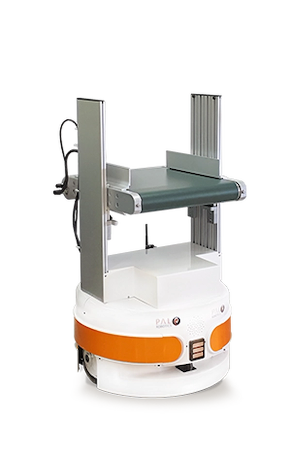
TIAGo Base Conveyor
Ideal for automating the loading and unloading of goods, this solution integrates a roller conveyor with the TIAGo Base. It’s perfect for handling deliveries, supplies, medication, or food, streamlining the transportation process within various facilities.
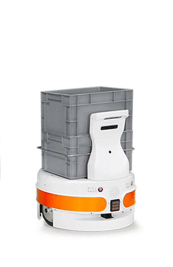
TIAGo Base Stackable Boxes Configuration
This setup is tailored for stacking and delivering a large number of boxes, making it an excellent choice for mail delivery in businesses or transporting food, medication, and medical supplies in hospitals.
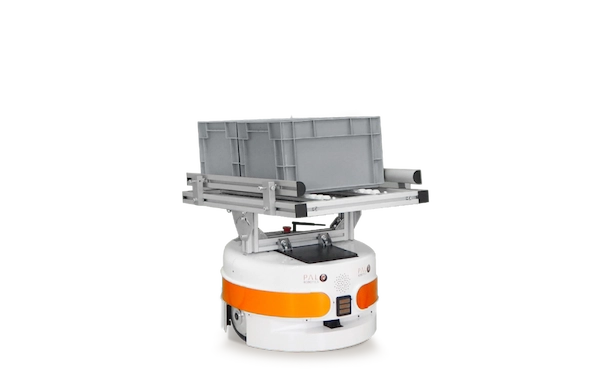
TIAGo Base Static Roller
Designed to load, move, and transfer any load in the warehouse. This configuration was developed with fixed conveyors for ease of transport and load.
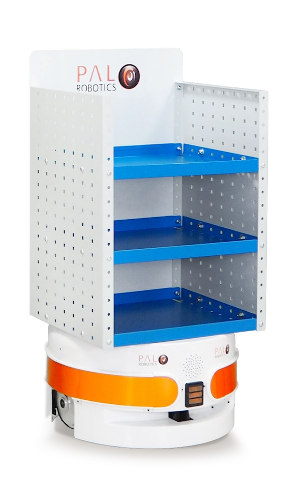
TIAGo Base Shelf
This integration aims to combine safety and productivity in one platform for easy loading, transportation, and delivery. Combining the shelf with 2 depth cameras, TIAGo Base Shelf is designed for dynamic work and tasks.
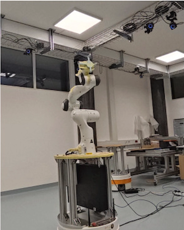
Frank Emika Panda Robot on TIAGo Base
This setup was done at the Jožef Stefan Institute by Tadej Petrič and Leon Žlajpah to perform a kinematic calibration on a mobile platform using a motion capture system. The setup consists of a Franka Emika Panda robot mounted on a plate on a TIAGo Base robot. The paper can be accessed here.
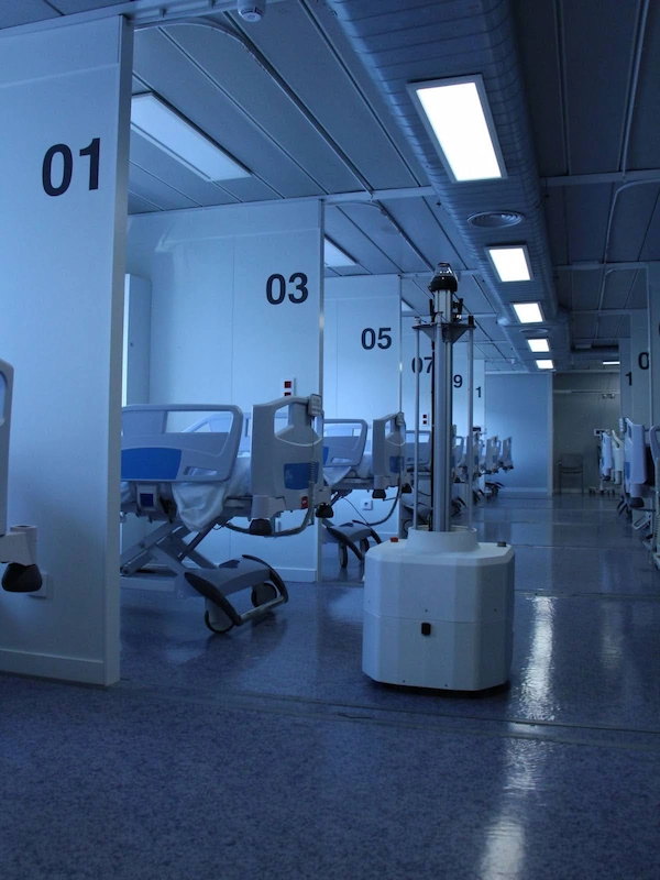
TIAGo Base Autonomous Disinfection Robot (ADR)
Featuring UV-C lights, the ADR is a powerful solution for cleaning and disinfecting public spaces and hospitals. This autonomous robot navigates efficiently, ensuring thorough disinfection faster than traditional methods.
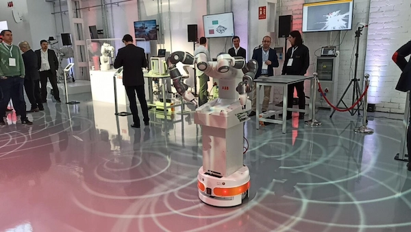
Collaborative Robotics in Healthcare and Industry
In a groundbreaking collaboration with ABB, the TIAGo Base has been integrated with ABB’s YuMi robot. In healthcare, this integration facilitates tasks like pipetting and tube handling in medical centre laboratories. In industrial settings, as seen in ABB’s Munich lab, it enables YuMi to serve multiple locations, enhancing mobility and versatility in collaborative robotics.
At PAL Robotics, we design and manufacture our products to meet your business needs. Our AMRs are customisable and adaptable to a wide range of applications, making them suitable for various industries. If you want to learn more visit our main website, and explore our range of AMRs to find the solution for your business. To ask any questions, don’t hesitate to contact us. Finally, to stay up-to-date with our latest news in tech and robotics, remember to visit our blog homepage.